2014-03-13
In case you have a question about a component please contact Ivan, OZ7IS, at "his callsign yahoo dk"
| Resistor | Nominal value | Delivered | Colour code |
| R1, R22 | 27 kΩ | 26,7 kΩ 27,4 kΩ 28,0 kΩ |
Red, Blue, Violet, Red, Brown, Red Red Violet Yellow Red Brown Red, Grey, Black, Red, Brown, Red |
| R2 | 10 kΩ | 10,0 kΩ | Brown Black Black Red Brown |
| R3, R14, R18 | 180 Ω | 182 Ω 178 Ω |
Brown Grey Red Black Brown Brown, Purple, Grey, Black, Brown, Red |
| R4, R7, R25, R29 | 22 Ω | 22,1 Ω 22,6 Ω |
Red Red Brown Gold Brown Red Red Blue Gold Brown |
| R5, R19 | 47 Ω | 46,4 Ω 47,5 Ω 48,7 Ω |
Yellow Blue Yellow Gold Brown Red Yellow Violet Green Gold Brown Red Yellow, Grey, Violet, Gold, Brown, Red |
| R6, R17 | 150 Ω | 150 Ω | Brown Green Black Black Brown (Red) |
| R8 | 8,2 kΩ | 8,25 kΩ | Grey Red Green Brown Brown Red |
| R9 | 2,2 kΩ | 2,1 kΩ 2,15 kΩ 2,21 kΩ |
Red, Red, Black, Brown, Brown Red, Brown, Green, Brown, Brown Red Red Brown Brown Brown |
| R10 | 1,2 Ω | 1,21 Ω | Brown Red Brown Silver Brown Brown |
| R11 | 5,6 kΩ | 5,62 kΩ 5,49 kΩ |
Green Blue Red Brown Brown Red Green Yellow White Brown Brown Red |
| R12 | 15 kΩ | 15,0 kΩ | Brown Green Black Red Brown |
| R13 | 1 kΩ | 1,00 kΩ | Brown Black Black Brown Brown |
| R15, R16, R24 | 39 Ω | 39(,2) Ω 38,3 Ω 40,2 Ω |
Orange White (Red) Red Gold Brown (Red) Orange, Grey, Orange, Gold, Brown Yellow Black Red Gold, Brown |
| R20 | 22 kΩ | 22,1 kΩ | Red Red Brown Red Brown Red |
| R21 | 3,3 kΩ | 3,32 kΩ | Orange Orange Red Brown Brown |
| R23 | 1,5 kΩ | 1,5 kΩ 1,54 kΩ |
Brown Green Black Brown Brown Brown, Green, Yellow, Brown, Brown, Red |
| R26* | 1 kΩ or 680 Ω |
1,00 kΩ 681 Ω |
Brown Black Black Brown Brown Blue Grey Brown Black Brown Red |
| R27 | 4,7 kΩ | 4,75 kΩ | Yellow Violet Green Brown Brown Red |
| R28 | 12 Ω | 12,1 Ω | Brown Red Brown Gold Brown Red |
| R30, R31 | 82 Ω | 80,6 Ω 82,5 Ω |
Grey Black Blue Gold Brown Grey Red Green Gold Brown |
| VR | 250 Ω | 220 Ω | Horizontal |
All resistors are 0,25 W/0,4 W and metal film type.
*: See changes below.
| Capasitor | Nominal value | Marking |
| C1, C7, C14, C24, C26, C32 | 120 pF | n12 |
| C2, C8, C28 | 27 pF | 27 |
| C3, C4, C30, C31 | 22 pF | 22 or 220 |
| C5, C6, C27, C29 | 1 pF | 1 |
| C9 | 270 pF | 271 |
| C10, C11, C25 | 33 pF | 33 |
| C12 | 3,3 pF | 3.3 |
| C13, C34, C35 | 39 pF | 39J 100V |
| C15 | 100 nF polyester, 2-modules | µ1K63, yellow or grey |
| C16 | 1 µF, 25 V, electrolytic, axial | 1µ0/25V (could also be a bit bigger) |
| C17, C18 | 22 µF, 25 V, electrolytic, axial | 22µ/25V |
| C19, C21 | 82 pF | 82 |
| C20 | 150 pF | n15 |
| C22 | 10 pF | 10 |
| C23 | 47 pF | 47 |
| C33 | 1 nF | 1n0, small yellow |
| C36, C37 | 12 pF | 12p, grey-green black top |
| C38-C59 | 10 nF | 10n, yellow green top/brown 103 |
All capacitors are 1 module, 2,54 mm, ceramic types unless otherwise stated.
| Component | Possible component | Delivered |
| D1, D2 | 5,6 V zener diode, 0,5 W | Blue |
| D3, D4 | 1N4004 or equivalent | 1N4006, black |
| D5, D6, D7 | 1N4148 or equivalent | 1N4148, red |
| IC1 | 78L08 | 78L08 |
| Q1, Q8 | BF988, BF981, BF900, BF960, BF961, BF964 | BF988, BF964 or BF961, text facing down, D long terminal, remember to mount ferrite beads |
| Q2, Q7 | J309, J310, U310 | J309 or J310 |
| Q3, Q4 | BD442, BD434, BD438, BD136, BD140 | BD442, Q3 metal facing west, Q4 metal facing east |
| Q5 | BC337 | BC337 |
| Q6 | BFW93, BFW92(A) | BFW92A, text facing up, C long terminal |
| Q9 | BFR96 | BFR96 or BFR96S, text facing up, C long terminal |
| Inductor | Type | Comments |
| DR1, DR8 | 6,8 µH 10 µH 12,5 µH |
Neosid, blue plastic cap, 6.8 Neosid, plain blue plastic cap Neosid, blue plastic cap, 10 |
| DR2, DR6 | 12,5 µH 18 µH 27 µH |
Neosid, plain blue plastic cap Neosid, blue plastic cap, 18, or no marking at all Neosid, blue plastic cap, 27, or no marking at all |
| DR3, DR4, DR5 | Ferrite bead | Run a piece of wire through the ferrite beads, big beads |
| DR7 | 15 µH RF-choke | Axial, Brown Green Black Silver |
| DR9, DR10 (Drain-choke) | Ferrite bead | To be mounted over Q1 and Q8 drain terminal, small bead |
| L1, L2, L3, L4, L12, L13, L14, L15 | Neosid 00 5231 03 | Grey metal housing |
| L5, L16 | Neosid 00 5061 00 | Marked 5061 |
| L6, L7, L8 | Neosid 00 5048 00 | The top is marked with yellow and grey dots |
| L9, L10, L11 | Neosid 00 5049 00 | Marked 5049 |
L1-L16: In case the inductor has a fifth terminal, one that is not located in a corner, cut it away. Please exercise the coil cores before mounting the coils as it helps tuning them afterwards.
| MX1, MX2 | SBL-1, IE500(A), IE800(F), HPF-505, SMC S-1. Pin 1 is marked with a blue/dark ring |
| Crystal | 42 MHz, third overtone, HC49/U |
| Metal sheet box | 148 x 74 x 30 mm3 |
| BNC-connectors | Four BNC-connectors. Remove the four terminals on each connectors. |
| Feed through capacitors | 3 x 1 nF, solderable into a 2,2 mm or 3,2 mm hole |
| Relay | FRT2SB-Sd |
| Metal sheets | Big on top side, small on bottom side |
| Adjustment tool | Light blue |
| 10 cm coax | Used in case of separate 28 MHz RX |
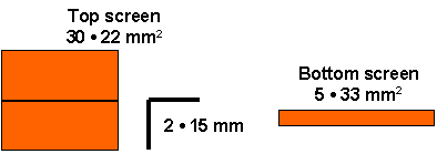
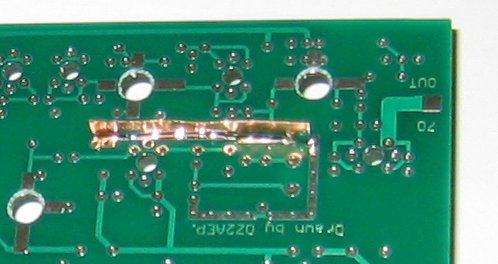
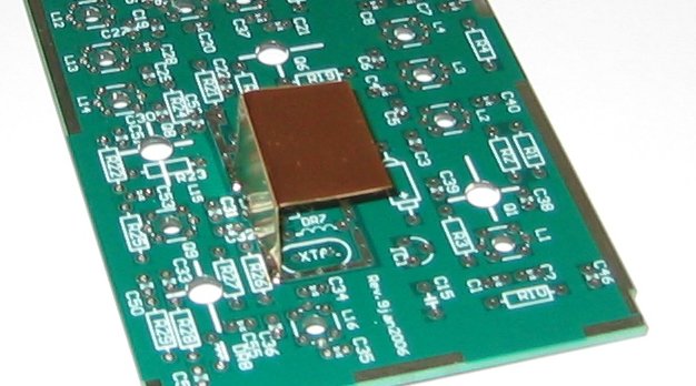
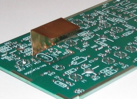
In order to reduce the leakage from the local oscillator two screens may be installed, one on the top and one at the bottom. The size of the screens are the minimum recommended ones. If you prefer you can make them bigger but it might be a bit difficult to service the transverter later on. These screens should be the last thing you mount on the PCB.
Figure 1. Size of bottom and top screens and how to bend the top screen.

Figure 2. Bottom screen.

Figure 3. Top screen.


Graham, G3LCT, suggests to put a ferrite bead on the drain of Q8, just like on Q1 to prevent instability.
Mark, GM4ISM, suggests to decrease R26 to 680 Ω to reduce the biasing of Q9. There is plenty of linearity on Q9 and lowering R26 will also lower the heat dissipation in Q9. Either R26 can be replaced by a 680 Ω resistor or mount a 2,2 kΩ in parallel with the existing 1 kΩ resistor.
Bo, OZ2M, www.rudius.net/oz2m