|
 |
|
2020-12-13
| Overview | VCO-PLL | DDS | GPS reference | Distribution amplifiers | Service management | Sequence | PI4 | Software |
|
|
|
Emanuele, IW9GDC - "... I can really say that this hardware is actually the best ever made ..."
The Next Generation Beacons uses GPS to synchronize both frequency and time. This done by using a GPS disciplined oscillator (GPSDO). The GPS reference can be used both as a beacon site reference but also as a station clock and 10 MHz reference in your shack and lab. If used as a station clock an additional display board must be used to show time and date etc.
All timing outputs are galvanically isolated to protect against static discharges. If needed voltage to the GPS antenna can be supplied via the coaxial cable.
If you have a GPS reference already with 10 MHz and NMEA outputs you can most likely use it for your Next Generation Beacons.
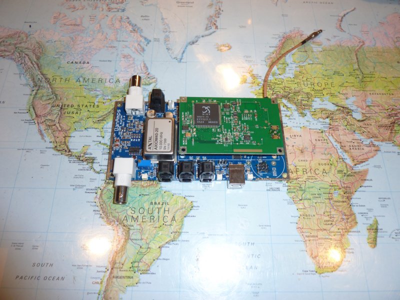
The 10 MHz is made using an AXTAL AXIOM40 high stability and low noise ovenized oscillator (OCXO). The GPS receiver is a Jupiter TU30. The 10 MHz signal is available from two galvanically isolated ports. The 1 PPS signal is available on two TOSLINK optical transmitters. The GPS data is available on a TOSLINK optical transmitter. A PLL lock signal is also available on a TOSLINK optical transmitter.
The GPSDO is designed with an analog holdover functionality in case the GPS signal is lost.
If you want to use more than one DDS board, i.e. you want to have more than one beacon on the air, you will need a NMEA distribution board.
For lab and home use you will need a 10 MHz distribution amplifier board if you want to connect more than one instrument or transceiver.
Empirical data show that GPS signals are not affected by the carriers even if many SHF carriers are on the air and close intermodulation wise to the GPS RF signal.
To use the GPSDO for a Next Generation Beacons unit it must be setup to only send the $GPRMC frame.
| DC characteristics | Unit | Notes | ||||||||||
| Voltage | 13,5 V to 15 V | |||||||||||
| Current | ~300 mA | After warm-up. During warm-up ~600 mA | ||||||||||
| Power consumption | <5 W | After warm-up. During warm-up ~7 W | ||||||||||
| RF characteristics | Unit | Notes | ||||||||||
| 10 MHz output | 0 dBm | Into 50 Ω | ||||||||||
| 10 MHz accuracy | 2 x 10-11 | 200 µHz at 10 MHz. 99% RMS accuracy after one hour warm-up | ||||||||||
| Phase noise | See table |
|
||||||||||
| GPS board ports | Connector | Notes | ||||||||||
| Supply | 2 pin Molex | |||||||||||
| RF connector | SMA/BMB/MCX | Depends upon GPS receiver used | ||||||||||
| 10 MHz out | 2 x BNC female | Galvanically isolated | ||||||||||
| 10 MHz lock | TOSLINK | |||||||||||
| 1 PPS | TOSLINK | |||||||||||
| NMEA Out | TOSLINK | |||||||||||
| Serial Out | USB B, female | |||||||||||
| GPS receiver | 10 and 20 pin connector | Designed for Rockwell Jupiter GPS receivers TU30 (included), TU40 and TU60 series | ||||||||||
| Display board interconnection, galvanic | 3 optical transmitters | NMEA, 1 PPS and 10 MHz lock | ||||||||||
| Display board interconnection, non-galvanic | 6 pin header or optical | NMEA, 1 PPS and 10 MHz lock | ||||||||||
| GPS board mechanical | Unit | Notes | ||||||||||
| Size | 146 mm x 72 mm x 40 mm | Fits into a standard tin plate box 148 mm x 74 mm x 50 mm | ||||||||||
| Weight | 150 g |
The price for an assembled, tested and ready-to-use GPS disciplined oscillator is around 3000 DKK*).
Additional shipping and money transfer cost applies.
*: Prices are subject to change due to exchange rate fluctuations and cost of components.
Here is a guide to troubleshoot an operational beacon including retrofits.
Please contact Bo, OZ2M, at my call sign @ this domain.
Bo, OZ2M, www.rudius.net/oz2m
