2022-11-29
RFzero
where it all starts
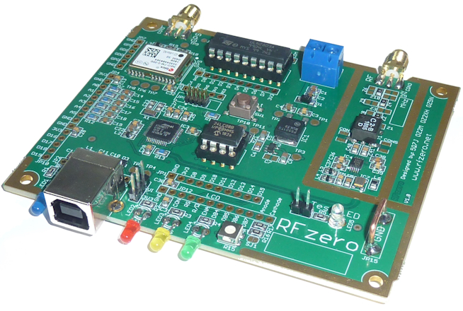
The RFzero is a multi
function Arduino RF platform developed for radio amateurs, RF enthusiasts and
everyone else who wants to extend the Arduino skills in combination with RF. The
RFzero board is largely
compatible with the Arduino Zero and Arduino M0 boards, however, it has been
carefully designed for flexible use in RF applications and with attention to the
frequency spectrum and stability performance.
The typical use of the RFzero
is as a beacon (IBP, SPB, CW, FST4, FST4W, FT4, FT8, JS8, JT9, PI4 and WSPR), signal generator, VFO,
Qatari Oscar QO-100 dual LO, Multi LO or a low cost 10 MHz GPSDO. More than 20 programs, Arduino sketches, are integrated into the Arduino IDE for easy upload to the RFzero.
The RFzero key features are
- GPS
- u-blox NEO-7M GPS receiver
- On-board pre-amplifier supply via coax
- SMA female input
- On-board header for GPS data access from other units
- Optional USB port directly to the GPS e.g. for computer time keeping
- RF
- Si5351A clocked at 27 MHz and measured continuously for maximum
accuracy
- Fundamental frequencies from 2289 Hz and close to 300 MHz
- Harmonics can also be used with reduced spectrum performance, e.g.
WSPR on 1 GHz is possible
- Usable for PI4 on 10 GHz via x96 multiplier
- Frequency resolution can be as low as 1 mHz
- Clock frequency measured continuously at 27 MHz for maximum accuracy
- Separate clock oscillator for maximum frequency stability
- Push-pull coupled outputs for more output and lower even harmonics, or
- Combined outputs for two-tone signals, or
- Quadrature I/Q outputs via U.FL sockets
- On-board pads for custom filter
- On-board RF decoupling
- RF section can be further shielded
- Separate voltage regulator for the RF section
- Four layer PCB for optimum RF performance
- SMA female output
- 13 dBm output 400 kHz to 200 MHz
- Micro controller
- Arduino compatible (Arduino Zero and Arduino M0)
- 32 bits ARM M0 processor running at 48 MHz and 10 PPM crystal clock
and with 32 kB SRAM
- 16 kB EEPROM
- Optional EEPROM in tulip socket
- USB port, with ESD protection, for programming and controlling
purposes
- ARM Cortex connector
- Four SPI ports
- Four I2C/Wire ports
- Five serial ports
- One Real Time Clock
- Four status LEDs (on, TX, GPS PPS and GPS valid)
- On-board LCD connector for either 3,3 V or 5 V LCD with contrast and
backlight control
- 28 I/O pins
- Up to eight 12 bits analog inputs
- One 10 bits analog (DAC) output
- The digital circuit has its own voltage regulator
- Darlington power driver IC ULN2803A in socket e.g. for controlling relays
- On-board test LED
- Possibility to add a shield for additional functionality or expansion
- On-board ground loop for alligator clip
- 11 test points for easy debugging
- Half Eurocard PCB size that fits into a variety of boxes including a metal
sheet box (Weissblechgehäuse) for best RF shielding
- Power supply via USB or 5 V to a terminal block
Bo, OZ2M, www.rudius.net/oz2m