2008-05-08
The purpose of this web page is to try to investigate some of the issues around ICOM IC-746PRO reported by many radio amateurs through out the world; and unfortunately not properly taken care of by ICOM.
If you are the owner of either the ICOM IC-746PRO or the IC-7400 you may already have experienced the issues. If not you may sooner or later. I have experienced all three generic faults: IC151 dead, ALC Jumping and LCD power supply failure.
Please note that I no longer own an ICOM IC-746PRO and I have not investigated any other problems than the three problems described below.
| Dead TX (IC151 RF Unit) | ALC Jumping (Q1/Q2 DRV Board) | LCD back light failure |
After having been the owner of an IC-746PRO for a good six months (August 2003) my TX started to drop in power, rapid drops though, and only visible when I transmitted 100% carrier type signals, e.g. FM, FSK441 or JT6M. At first I thought it was RF feedback but why now? I had not rearranged my shack or cabling.
I already knew of the Dead TX issue of the IC-746PRO and it seemed to fit like a glove with my experience.
It all seems to relate to one single component: IC151, µPC1678G, P/N 91213606, and overheating. 100% type carrier signals, i.e. FM or digital, just made it easier to see.
Roomers are that ICOM says that it is no longer a problem after (re-)installing a few anti Electro Static Discharge components. According to ICOM America S/N after 3550 (if URL fails which I think it does or ICOM has removed the page, take a look here how it looked like), initial numbering principle, should be OK from the factory. Comments are indicating that the ESD originates from HF antenna. The S/N numbering principle has been changed sometime during 2003, starting with 02#####, seven digits, and should also have the anti ESD fix from the factory.
Firstly, my IC-746PRO has S/N 3623 and the TX has failed. Secondly, there is very little chance that ESD is the reason in my case since my HF antennas are located under the roof, furthermore do I hardly ever use HF. Thirdly, I have a 70 MHz transverter permanently connected to the ANT 1. Finally, I also use a sequence controller to manage the switching sequence in order not to switch anything with HF on it. You can see a schematic of my station set-up here.
It might be that ESD can kill the IC151, over night and completely, but I do not believe that ESD has anything to do with over heating that is an even more plausible cause and in my case seen as a slow degradation. But when ESD does happen it, probably, shows as instant death, i.e. the very next time the transmitter is activated. In some cases this may be one week later or even later. Not everybody transmits everyday.
When it comes to a fix for the ESD ICOM seems to have taken the issue into a retrofit policy if rigs are returned for repair, ESD related or not. So far so good. Any non ESD protected device is always more sensitive to an ESD hit, whether it is 1 kV of 10 kV. ESD protection is a real pain in any electronic device.
100% carrier type signals or not the problem will most likely show up no matter what S/N you may have.
I have stolen the below comments from www.mods.dk where Karel, OK1DNH writes:
»Very common failure of device IC 746 746PRO, 756, 756PRO and 7400 is destruction IC uPC1678 (driver for PA). This is draft mistake, which ICOM company don’t want to accept. ICOM company stays on idea, that this driver IC failed only by static electricity from HF antenna (in this case other two capacitors and two diodes must be destroyed, but these components are after destruction of this driver IC still heath) and even they released service note, where they recommend add diodes to input of HF receiver. And on IC 746PRO from S/N 3300, they add this diodes in factory.
BUT I had on my table IC746PRO S/N 3422 with factory installed these diodes and driver IC was DEAD. And components on static electricity path are still healthy. Construction problem is somewhere else. Author leaves this IC under power also in receive state, which main mistake is. IC has idling current about 50mA and produce heat in receive regime. In radio transit regime „eat“ higher current and also higher temperature. A now we are in construction problem. Producer of this IC uPC1678 in application note describe, how big must be minimal area of copper on PCB for good cooling. This IC is cooled only through legs!!!!! And this was by ICOM absolutely underestimated, beside minimal area of copper with dense area of connecting hole about 6cm sq. In IC74X device are only about 1cm sq. of flat and thereby also cooler. This is reason why this IC heats till overheat deal. From IC 74X production start I replaced about 20 this IC, and this is reason why I start to search where is problem. Problem can be solved by adding some cool wing connected to device chassis, but in possible mounting place body is not flat, but rounded. Or is possible to think about switching off this IC in receive mode.
If I talk about underestimating of cooling areas, there is another place in IC 74X, regulation transistor of display light converter. So lower display light intensity user set, so higher heat is produced by regulating transistor. Due absolutely minimal cooling area, on which is this SMD power transistor soldered, very soon came to “baking” of this transistor.«
Since the ICOM IC-746PRO is part of a family of transceivers it might be an idea to compare the µPC1678G circuits in the various radios. It is quite remarkable that the "same" component also uses the same component ID in the radios - I would say. This could indicate that the design idea is reused which is not a bad thing at all.
There seems to exist two versions of the IC-746PRO IC151 circuitry.
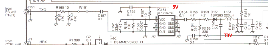
ICOM IC-746PRO IC151 circuitry. Source: ICOM IC-746PRO Instruction Manual. Scanned from my own Instruction Manual.
ICOM IC-746PRO IC151 circuitry. Source: Documentation found on the web.
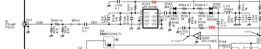
From the above schematics it can be seen that IC151 is permanently connected to +5 V through R157. An easy and cost effective solution.
Since the IC-746PRO is the follower of the IC-746 it is interesting to see how ICOM did the design in this radio.
ICOM IC-746 IC151 circuitry. Source: ICOM IC-746 Service Manual.
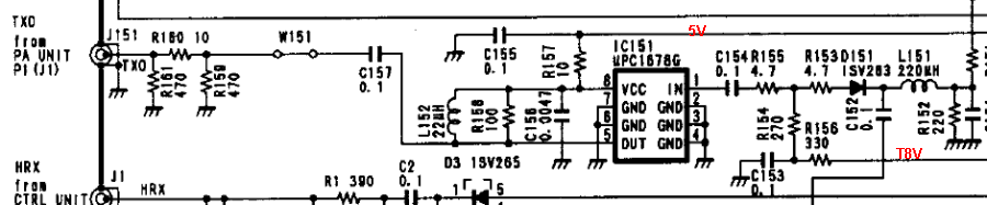
As it can be seen the circuitry is identical to the one found in the IC-746PRO. So could it be that the IC-746 is just as likely to fry the µPC1678G? Sergey L. Chuchanov has posted a message addressing this issue named "Solutions for chip blowing with mPC" back in 2001-10-20. The solution is debated but none the less the issue is acknowledged.
Another part of the IC-746 family is the IC-756 Series. The first transceiver in the family is the IC-756 that also uses the µPC1678G.
ICOM IC-756 IC801 circuitry. Source: Documentation found on the web.
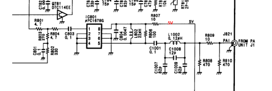
As can be seen in the above the IC801, µPC1678G, is permanently connected to the 5 V line and the topology is identical to the one of found in the IC-746 and IC-746PRO.
When ICOM introduced the IC-756PRO the design around the µPC1678G was changed to the more complex one found below.
ICOM IC-756PRO IC151 circuitry. Source: Documentation found on the web.
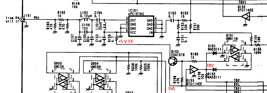
Not only does the IC-756PRO feature TX Switched 5 V supply of the µPC1678G but also lowpass filtering of the RF output, L152 120 nH, C156 12 pF, C155 82 pF and C157 82 pF.
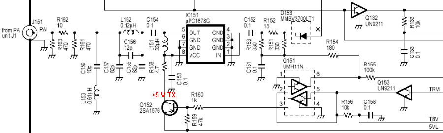
ICOM IC-756PROII IC151 circuitry. Source: ICOM, IC-756PROII Instruction Manual.
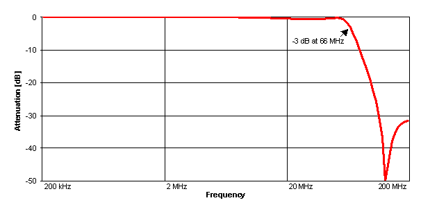
The response curve of the lowpass filter shows a -3 dB cut off at 66 MHz thus the filter cleans up signals relevant for the IC-756PROs. If a similar idea should be implemented in the IC-746PRO component values would have to be changed to allow 144 MHz to pass. But I find it hard to believe that the lowpass filter has anything to do with the life and dead of the µPC1678G.
Lowpass filter found in the IC-756PRO and IC-756PROII.
One reason for introducing the filter in the IC-756PROs could be that switching the supply voltages causes the µPC1678G to show a higher number of spurs, which I doubt.
How has ICOM done the design in other HF + VHF radios? This page shows some more designs.
The circuitry in the IC-746PRO is simpler than in the IC-756PROII primarily that in the IC-746PRO the supply voltage is not switched on when IC151 is needed, i.e. during TX.
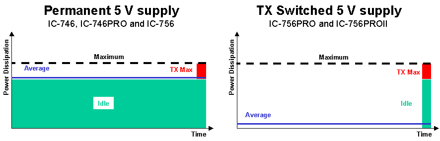
In professional radio products the design guide is 90% standby, 5% RX and 5% TX. If similar rules are applied in the IC-746PRO IC151 is idle 95% of the time and 5% TX, but in the IC-756PROII there is no idle only 5% TX.
The power dissipation in idle is 250 mW and the maximum power dissipation, PT, is 330 mW according to the datasheet for the µPC1678G, the Application Note is here. These two power levels are pretty close when the IC151 is idle 95% of the time. The only cooling IC151 gets is through the ground pins, 2-4 and 6-7 and as Karel, OK1DNH, points out there is not sufficient ground track on the PCB to provide proper cooling.
Comparison of the power dissipation in the two different topologies, permanent and TX Switched 5 V supply.
Unfortunately I have not had the chance to look inside any of the IC-756PROs. But Dietmar, VE3CG, was kind enough to send me some pictures from his IC-756. When comparing the PCB found in the IC-746PRO with the one in the IC-756 there seems to be more ground track and more plate throughs in the IC-756 that will provide better cooling, and still ICOM decided to abandon this design for the IC-756PROs.
All this could indicate that the over heating of IC151 in the IC-746PRO IS THE ISSUE.
Actually the solution may come in several flavours:
I cannot say that the Electro Static Discharge is the main reason for the fault but I suggest that if you are about to change your µPC1678G mount the anti ESD components as well.
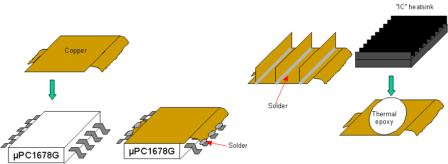
Suggestions for increased cooling of the IC151 circuit.
So far I have not tried neither of the above solutions. But my TX is about to fail completely anytime soon. So I will have to once I get the replacement IC151. An alternative solution to 4. could be to use the T8V and four diodes to drop the supply voltage at pin 8 down to 8 - 4 x 0,7 V = 5,2 V. I think that is the solution I will try first.
The "right" solution is the IC-756PROII one where the IC151 has switch supply voltage. However, ICOM may have decided otherwise due to cost in the IC-746PRO. I cannot say but the additional LC-filtering on the output may be needed when such a solution is used.
Herb, VE7AZC, has made a small hoop out of some copper sheet.
Dietmar, VE3CG, has glued a transistor heat sink onto the top of IC151.
See more of Dietmar's installation here. The heat sink might seem a bit high but will fit nicely between the metal cover and IC151. The ATU Molex connector might look as if it could be in the way but it is not.
GW8IZR
Paul, GW8IZR, crafted this neat solution for his IC-746.
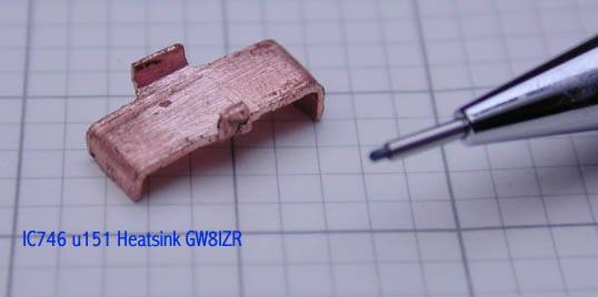
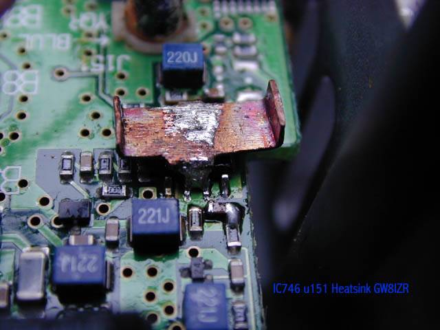
The sink is fairly heavy copper and required a bit of heat trauma to get it in place but most of the heat wanders off into the ground plane while fitting so it should be ok. Paul also points out that he has removed ATU Molex connector. So have I, OZ2M, but my TX still failed.
K5LXP
Mark, K5LXP, has made a very thoroughly documented home page with lots of information and pictures too on how he repaired and improved his IC-746PRO.
Some might say that ICOM will find a solution to the over heating problem. Well, they have for some reason done this in the IC-756PROs, and other radios, but has continued with the design in the IC-746PRO that was rejected in the IC-756.
On 2004-02-22 this ICOM America webpage was reported (if URL fails which I think it does or ICOM has removed the page, take a look here how it looked like). I filled in the form on the same day but as of 2004-03-10 I have not been contacted by ICOM America. I bought my IC-746PRO from Gigaparts and I picked it up myself in San Diego as it was shipped to a a friend of mine. Thus fully "ICOM America turf."
In order to get as many facts as possible please provide me with your details to this failure record sheet.
My IC-746PRO has S/N 3623, so protection diodes were factory installed, but still the TX died
I have made zero (0) QSOs on HF with it, I use it for transverter IF and I never use the tuner.
My TX began to fail after six months. I replaced the IC151 and the radio is OK again.
My radio is grounded.
I use a highly sensitive pre-amp on 2 m, that has never burned.
I key my external devices, i.e. relays, PAs and transverter, and the IC-746PRO, the heart, from a sequenced controller, the brains.
There is a substantial number of IC-746PROs having dead TXs.
ESD is not the reason my IC-746PRO TX died.
The same number of IC-746 having a dead TXs is far from the IC-746PRO numbers. Why that is I do not know but some have reported a dead TX. Perhaps there is more ground track in the IC-746 and better air circulation.
ICOM America says that they have not seen any discolouration on the PCB around µPC1678G. Well, if most of the heat stays inside the µPC1678G chip then no discolouration will be seen on the PCB.
If you are looking for a new radio should you choose to buy an IC-746PRO? I think you can find many positive arguments for buying an IC-746PRO, and if you, in the more or less unlikely event, are not afraid of replacing the IC151 yourself go ahead and buy the radio. It is neither difficult nor expensive, a µPC1678G costs around 5 € if you buy only one. On the other hand if you are not comfortable with repairing your own radio do not buy it. Of cause you can always send it to a skilled repair shop. So make your choice.
Who is right and who is wrong? Is this "Dead TX thing" just a vicious roomer? Well, I do not have the same quantity of either IC-746PROs or µPC1678G that ICOM has. I may be able to afford a dozen of µPC1678G but a dozen of IC-746PROs for testing purposes under identical conditions is not within my priorities.
Why did ICOM abandon the permanent 5 V supply of the µPC1678G in the
IC-756PROs and other radios?
It
is a more complex design, and more components that could lead to a lower
production yield. ICOM could have introduced the lowpass filter if needed to
clean up the signal, without changing the IC151 circuit, and this is probably not directly related to over heating of the µPC1678G.
What is the quantity of radios produced and sold with S/N below 3551 and how many after?
What is the number of returned radios both splits?
It is ICOM Americas perception that the ESD fix has reduced the number of dead TXs to 10% of previous numbers. ICOM America might be right, and they might be wrong. I think they are right that the ESD fix has stopped some µPC1678G from being destroyed. But how can they ICOM tell?
In August every year (August 2005) the time for meteor scatter QSOs peaks and at the same time also the temperature inside and outside my house. This year was no exception either. MS QSOs require a lot of TXing and RXing continuously for longer periods.
For some time I had experienced some rapid power drops, but, this time the IC151 was working as it was supposed to. Actually I think this problem was also present when I had the IC151 problem two years ago. I also discovered that changing the power on the front panel made the ALC misbehave for up to 10 s or so. Sometimes the carrier would rise slowly after starting to transmit.
Furthermore have some neighbour amateurs from time to time complained about my modulation on SSB.
So I dived into the numerous archive ones more. I found that the DRV Board FETs, 2SK2975, have been changed in a number of radios due to leaky bias current issues - whatever that is in ICOM terms.
Before doing anything I decided to make some experiments. Off with the covers etc. and let the radio breathe. It helped. I also tried to cycle the temperature around the FETs from solder iron temperature to cooling spray. It made the ALC Jumping stop for a while. However, I could not help poking a finger on the FETs.
Argggggggghhhh!
The one to the left, Q1 2SK2975, gets extremely hot even with a total output of only 25 W. The right one stays a bit colder.
Well, even without applying any RF out the temperature difference is quite big and the left one, Q1, gets fairly hot. But can be touched.
So I also made a set of my measurements with an infrared thermometer where the probe head is about 1 mm above the surface of the transistors. It cannot get any closer. The measurements were carried out at key down in either SSB (no modulation/RF) or 25 W CW at 100% duty cycle.
Table 1. Just switched on radio, no RF, i.e. bias only. Source: own measurements.
| Time [s] |
Q1 temp [°C] |
Q2 temp [°C] |
| 0 | 25 | 25 |
| 5 | 39 | 26 |
| 10 | 44 | 26 |
| 15 | 46 | 26 |
| 20 | 47 | 26 |
| 25 | 48 | 26 |
| 30 | 48 | 26 |
| 40 | 48 | 26 |
| 50 | 48 | 26 |
| 60 | 48 | 26 |
Table 2. Radio has been on for three hours, no RF, i.e. bias only. Source: own measurements.
| Time [s] |
Q1 temp [°C] |
Q2 temp [°C] |
| 0 | 32 | 35 |
| 5 | 54 | 35 |
| 10 | 61 | 35 |
| 15 | 66 | 35 |
| 20 | 68 | 35 |
| 25 | 70 | 35 |
| 30 | 70 | 35 |
| 40 | 71 | 35 |
| 50 | 71 | 35 |
| 60 | 71 | 35 |
Table 3. Radio has been on for three hours, 100% duty cycle, 25 W CW. Source: own measurements.
| Time [s] |
Q1 temp [°C] |
Q2 temp [°C] |
| 0 | 32 | 32 |
| 5 | 76 | 33 |
| 10 | 87 | 35 |
| 15 | 91 | 36 |
| 20 | 94 | 37 |
| 25 | 96 | 38 |
| 30 | 97 | 39 |
| 40 | 98 | 39 |
| 50 | 98 | 40 |
| 60 | 99* | 41 |
*: 1°C more and I can use my IC-746PRO for boiling water.
It looks like I have to replace the driver transistor(s) and perhaps add another heat sink solution to my radio.
Now what does this mean to you? Well if your 2SK2975 transistors behave it should not be a problem. However, I would advise you to verify the temperature in your own radio. If you observe the same as I do you probably want to get a pair of 2SK2975 for the day they are gone. If you already have the ALC Jumping you are probably in a similar situation to mine.
OK what will ICOM say I am doing wrong this time? I haven't got a clue. They have never responded to my IC151 form submission. My radio was purchased to my previous San Diego address. "No problem, the serial number will take care of this." Well, it might. My S/N is 3623.
I finally managed to prioritise the repair of the driver board in my IC-746PRO. In stead of the 2SK2975 I decided to give it a try with the RD07MVS1. The advantage of this FET is that it is a newer design, cheaper and easier to find on the market. The driver stage circuit is not a tuned circuit. Therefore the RD07MVS1 should do just fine even if it has a bit higher gain.
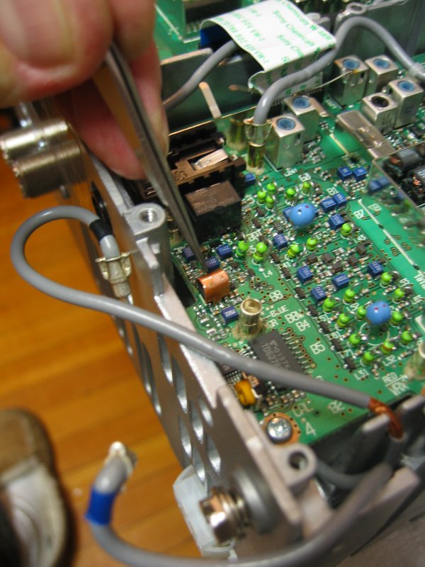
The tricky part is desoldering the existing 2SK2975 FETs from the DRV Board. First you must remove the two screews holding the board to the chassis. Secondly you must desolder the board from the four 4 pin connectors. Use Solderwick or similar to remove the solder. Third step is to desolder the FETs. The easiest way to do this is with a hot air soldering gun and soldering iron. If you can find a friend to help you out it is a good idea as two pair of hands will come handy. You may even pre-heat the DRV Board heatsink using another soldering iron.
Once the FETs have been removed clear the free gate and drain pads on the PCB and the heat-sink pads too.
To install the new FETs, 2SK2975 or RD07MVS1, pre-heat the DRV Board heatsink and and put a thin layer of solder on the gate and drain pads. Then place the new FETs on the PCB. Make sure you align them carefully within 1 mm. Otherwise the source will get in contact with either the gate or drain pads. Add a bit of solder to the source on both sides of each FET. Make sure the FETs rest as close to the PCB and heatsink as possible. Otherwise cooling the FETs will become a problem as solder is a bad heat conductor.
Before you re-install the DRV Board assembly apply a thin layer of thermal compound to the DRV Board heatsink. Keep in mind that the thermal compound itself does not cool the devices it helps to increase the thermal conductivity so apply a thin layer. Do not soak the metal surfaces in thermal compound.
Thanks a lot to Jørgen, OZ1BNN, for helping with replacing the DRV Board FETs.
This section applies even if you have not yet experienced problems with your DRV board FETs.
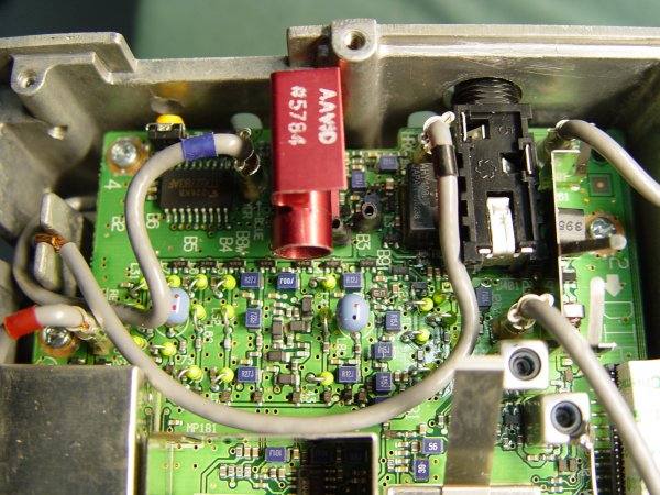
To further increase the cooling of the driver FETs I have made a funnel using three pieces of card board taped together. This "modification" will focus the air flow on the top of the PA PCB to pass the DRV Board before continuing over the final PA FETs and through the holes in the back of the chassis.
Card board funnel.
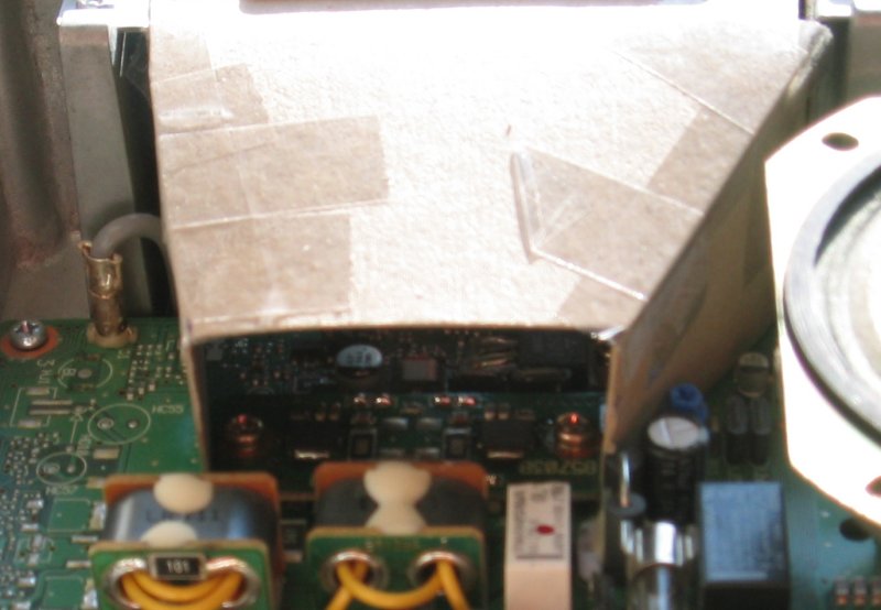
The three pieces of card board can easily be positioned between the fan and the frame supporting the fan on the top side of the PA PCB.
This section applies even if you have not yet experienced problems with your DRV board FETs.
Colin Maddock from New Zealand was kind enough to send me a file made by Bill Leahy, K0ZL, from B&B TECHNICAL SERVICES addressing the biasing of the driver stage. Here is ICOMs service bulletin on the issue. I have only replaced the driver FETs because they were bad and adjusted the bias. I have not changed the other components mentioned in the ICOM document.
I fully agree with the document and applying 2-2,5 A for a 6-7-8 W stage is a lot of bias. As pointed out in the document 35 W is a lot of power to dissipate through a small surface like the source pads.
Furthermore if you happen to have one bad intermodulation report it is better than having no reports at all - i.e. if your DRV Board is completely dead! You can always increase the bias to the right, but still lower, level.
Table 4. Bias measurement. Source: own measurements.
| Scenario | Total current consumption [A] |
| RX only, before adj. | 2,07 |
| TX, before adj. | 5,50 |
| TX, R11 fully CCW | 3,05 |
| TX, "right level" | 3,60 |
So my bias is now 550 mA and on air reports are good. I have not done any real two-tone IMD measurements on a spectrum analyser. But on air tests report no IMD problems.
Table 5. Radio has been on for three hours, no RF, i.e. bias only, without card board funnel. Source: own measurements.
| Time [s] |
Q1 temp [°C] |
Q2 temp [°C] |
| 0 | 27 | 28 |
| 5 | 32 | 36 |
| 10 | 32 | 38 |
| 15 | 33 | 39 |
| 20 | 33 | 39 |
| 25 | 35 | 39 |
| 30 | 37 | 40 |
| 40 | 37 | 40 |
| 50 | 37 | 40 |
| 60 | 37 | 41 |
Table 6. Radio has been on for three hours, 100% duty cycle, 100 W CW, without card board funnel. Source: own measurements.
| Time [s] |
Q1 temp [°C] |
Q2 temp [°C] |
| 0 | 28 | 28 |
| 5 | 47 | 53 |
| 10 | 48 | 55 |
| 15 | 49 | 56 |
| 20 | 50 | 54 |
| 25 | 51 | 57 |
| 30 | 52 | 58 |
| 40 | 53 | 60 |
| 50 | 54 | 60 |
| 60 | 55 | 60 |
As you can see from table 4 and table 5 there is still a small spread in the temperature between the two DRV Board FETs which must be due to the fact that the FETs are not matched and the bias adjustment is done for both FETs using the same gate voltage.
I strongly recommends this bias "modification" to anyone having an IC-746PRO. Better today than tomorrow.
I had this failure too, but, I did not take any pictures of it.
The issue is the power switch FET that fails. This result is that the back light in the LCD fails. To change the FET you need to remove the knobs and front cover from the chassis as well as ribbon cables inside the radio. This can seem rather scary but take your time and you can do it too.
There is plenty of documentation on the web about this problem.
Just a note on my personal background: Electrical Engineer and five years at the Motorola R&D in Copenhagen working as Senior RF Design Engineer.
Bo, OZ2M, www.rudius.net/oz2m